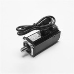
1. Initialization parameters
Before wiring, initialize the parameters.
On the control card: select the control mode; clear the PID parameters; turn off the default enable signal when the control card is powered on; save this state to ensure that the control card is in this state when it is powered on again.
On the servo motor: set the control mode; set the enable by external control; the gear ratio of the encoder signal output; set the proportional relationship between the control signal and the motor speed. Generally speaking, it is recommended that the maximum design speed in the servo operation corresponds to the control voltage of 9V. For example, Sanyo sets the speed corresponding to 1V voltage, and the factory value is 500. If you only plan to make the motor work below 1000 rpm, then set this parameter to 111.
2. Wiring
Power off the control card and connect the signal line between the control card and the servo. The following lines must be connected: the analog output line of the control card, the enable signal line, and the encoder signal line of the servo output. After reviewing that the wiring is correct, power up the motor and control card (and PC). At this time, the motor should not move and can be easily rotated with external force. If not, check the setting and wiring of the enable signal. Rotate the motor with external force and check whether the control card can correctly detect the change of the motor position, otherwise check the wiring and setting of the encoder signal
3. Test direction
For a closed-loop control system, if the direction of the feedback signal is not correct, the consequences must be catastrophic. Turn on the enable signal of the servo through the control card. At this time, the servo should rotate at a lower speed, which is the legendary "zero drift". Generally, there will be instructions or parameters for suppressing zero drift on the control card. Use this command or parameter to see if the speed and direction of the motor can be controlled by this command (parameter). If it cannot be controlled, check the analog wiring and parameter settings of the control mode. Confirm that a positive number is given, the motor rotates forward, and the encoder count increases; if a negative number is given, the motor rotates reversely, and the encoder count decreases. If the motor is loaded with limited travel, do not use this method. Do not give excessive voltage during the test, it is recommended to be below 1V. If the directions are inconsistent, you can modify the parameters on the control card or motor to make them consistent.
4. Suppress zero drift
In the closed-loop control process, the existence of zero drift will have a certain influence on the control effect, and it is best to suppress it. Use the parameters on the control card or servo to suppress zero drift, and adjust carefully to make the motor speed approach zero. Since the zero drift itself has a certain randomness, it is not necessary to require the motor speed to be absolutely zero.
5. Establish closed-loop control
Release the servo enable signal through the control card again, and enter a small proportional gain on the control card. As for how small it is, it can only be based on feeling. If you are really worried, enter the minimum value that the control card can allow. value. Turn on the enable signal of the control card and servo. At this time, the motor should have been able to roughly act according to the motion command.
6. Adjust the closed-loop parameters
Fine-tuning the control parameters to ensure that the motor moves according to the instructions of the control card, this is the work that must be done, and this part of the work is more experience, so it can only be omitted here.